This CD player was built in 1986 and retailed for $400. It is nicely built, but not nearly as sophisticated as the Sony CDP 650ESD that graced these pages recently.
This post is mostly an excuse to share this link and this second link. These sites contain pretty much identical lists of cd players and identifies their DACs and transports. Cool, but why? you ask.
Well, some people are really obsessive about their DACs and transports. Just google TDA1541 and see what you get.
For the record the PD 5010 uses the Sony CX20152, a dual, 18 bit, two times oversampling DAC. You can see it at the right, above. In the previous picture it is in the far upper right. Note the nice film caps in the output stage to the left of the DAC. The clear ones are styroflex.
Sunday, December 6, 2009
Li' Mar: Making the Best of a Difficult Situation
Ahh, we are back to that troublesome little Marantz, are we? Yep. She has not been forgotten, although it has been tough to tell from this blog. I have been avoiding her.
In our last adventure (It was when??? October??) we made some progress by pulling a wobbly post off the preamp board. That solved a problem, but progress always seems to be followed by a setback with this amp.
Way back in August (!) I had recapped the amp board, and I vaguely recall checking the output transistors, but evidently I was not exactly thorough. With the preamp playing a bit better it was clear that the left front channel had an odd distortion. Mike ran it through the ocilloscope and exactly half of the wave form was missing. Literally. One of the 8 outputs was bad and I had either missed it or it had recently failed. Its mate was working on the positive swing, but the zero line was as far as the signal went.
When one is bad, replace them both.
Here is the board, pulled yet again. The replacements are the clean ones at the left.
Here is the heat sink and goo, the imprint of the dead output is the incomplete one at the top. Hmm, maybe it didn't seat well enough... No need to wallow, there is more trouble ahead!
Replacing an output isn't particularly difficult, but what followed was.
The preamp board: what a pain in the butt. The front channels seemed ok, although once in while it seemed... off. The rear channels were maddening. The treble was behaving like a combination tone control and volume pot all in one. The signal would disappear. The bass pot was more stable, but every once in a while it would distort. Maybe it was salvageable, but that treble pot was more a 'trouble pot'. I chased bad solder joints and bridges for far too long, and finally threw in the towel.
I talked all this over with Mike. His strong suggestion was to cut my losses and just run both front and rear outputs with the front section of the preamp. This was a very easy modification, but I really didn't want to sacrifice the quad features of this amp. I was hoping we could just jumper the rear channel treble pot and salvage as much as we could. Mike did not like this idea at all, too complicated and too many problematic components remained in circuit.
Before we could decide on a plan of attack, life intruded, and Mike had to leave for several weeks to visit his father in Midland. This has been a very tough year on our parents.
This past Saturday we finally had a good day on the bench. We settled on a reasonable plan of attack, and most importantly, Mike did most of the dirty work. So, next time, I promise I will have some good news about Li'l Mar.
Sunday, November 15, 2009
The Very, Very Rare Sony CDP 650ESD CD Player
This statement piece from Sony Esprit was built in February, 1986 and retailed for $1300. This unit clearly spent its last years in a garage since the back half was completely coated in fur. I spent a good hour cleaning it with cotton swabs and fired it up. It came up nicely on the Sencore Powerite, but the drawer wouldn't open: as usual the rail grease had become rail sludge. So, another 10 minutes of swabbing followed by the oil got the door to open.
There is almost no information on this player on the web. For comparison purposes here is the write up on a Sony CDP 302 from '85 and the very similar Sony CDP 520ES.
This player is very heavy and chock full of copper. It is also chock full o' boutique caps, mostly Elna Cerafines and a few Blackgates. There are 6 op-amps in the analog stage that have copper heatsinks mounted on top, which can be seen at the upper right of the picture below:
The transport is complex:
The drawer action was a bit slow and it skipped occasionally, so we opened the bottom:
Mike said the skipping was caused by a sticking sled, and he was correct. The 650ESD played very nicely post lube. I changed one belt, somewhat unsuccessfully. The second was trickier to remove so I blew it off. My choice of replacement belt was not very good, the drawer action was actually worse afterwards. It will have to wait until next time.
Here is the bottom of the transport. The laser is on a sled that slides front to back, right to left in the photo below. The two belts are at the left, around the white plastic pulley.
This 650ESD is noted as the first cd player with digital out and it is housed in a pod sticking out of the back. Odd. The switch says 'On', 'On (For Audio Use)', and 'Off'. I am not exactly sure the how the two 'Ons' differed. And it has 3 play modes, I am not sure how that works. I might actually have to procure a manual and suffer the resulting testosterone loss.
And a nod of appreciation to Sony, c. 1986.
This is a spectacularly designed and built player. I am not sure what is next beyond belts. There are a few caps that could use a freshen-up, but it is tough to replace Cerafines with anything other than Cerafines. Time to do some research.
Sunday, November 1, 2009
Odds and Ends, Again
Not much to write, but here are a few interesting photos. First up, a CM Labs 911 solid state power amp. Orion says it's from the early 70's but it looks very 60's.
The sides are cast:
According to Mike the build quality is superb, akin to McIntosh of the era.
UPDATE: Rummager has commented on the Bozak and CM Labs connection. Here is a very interesting web site by Bob Betts, several times chief engineer for Bozak. It includes a photo of Wayne Chou. The name CM (or C/M) Labs was a contraction of Chou and Morris. Here is a link to a DIYAudio wiki with information supplied by Wayne Chou. The above amp is from 1966 (!) and was named after the Porsche. CM Labs even produced a speaker, the CM-15, that was designed by Houston's own Louis Erath. (One of these days we hope to have a long write up on Mr. Erath. We have a source!) Thank you for the tip.
Next up, my very early Sansui mono pre/power combo. I assume this is from the 50's. The label on the front says this is an FM 15.
The outputs are 6V6. Note the substantial and lovely output transformer:
And last but not least is the volunteer papaya plant growing in the alley behind Austin Stereo:
Tuesday, October 27, 2009
In Celebration of Speaker Day
Around our household we celebrate a number of unusual holidays. One of my favorites (and my wife's) is Speaker Day. On this day all adult males haul out the speakers they have been storing in closets and unused bedrooms and make them ready for the next stage in their lives. While not as festive as the International Day of the Sock, it nonetheless is a lot of fun. Speaker Day could be celebrated pretty much every week around our house.
After a two year drought and a summer of screaming heat, Austin is evidently now enjoying a fall monsoon, so Speaker Day was at risk this past Sunday. But the sun was sort of out, and the ground was sort of dry, so it was on with the celebration.
The star of the festivities was this bottle:
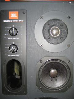
Yes, that is a really old bottle of Sta-Wax I found at an estate sale. (Guess how much I paid for it.) This stuff has an odd, strong smell, sort of like cherries, but it is a wonderful product. It should be used much like lemon oil, but it is much more effective. It is great on open grain wood like the JBL 4410 it sits on. The photo doesn't do it justice: the right half has been treated and the left half hasn't.
Next up, a classic marriage killer:
This is a Knight 2300C speaker in very lovely dark walnut, or maybe mahogany. If you are the sort of husband who can't bear to leave a pair of large real wood speakers to the hazards of a thrift store, be forewarned. You will be shocked to learn that the wife will not like them. Too honkin' big. But if you do save them from further insult at the hands of barbarians, you will discover they have nice Jensen drivers. The 10" woofer is one of their better finished models, with a horn mid and a very interesting looking tweeter. The crossover is nicely done and worthy of some cap rolling fun and games. Oiled up they look great.
Onward to a long sought after speaker: the Optimus 10. Long ago (as in at least 30 years ago) I read a very nice review on them and thought I would like to give them a listen. Time passed... This is the one an only pair I have ever seen and I literally pulled them out of a huge salvage box at our crazy Goodwill dumping ground. The grill was shattered and the foam surrounds were long gone. I out them back together and even put a nice cap on the tweeter. It is just amazing what a male of the human species will endure for the love of a loudspeaker. The Optimus 10 has a decent dome tweeter with an 8" woofer and a 10" passive radiator. And the tweeter control even has a nice response curve which no doubt is completely accurate. I have yet to give them a real listening, though, I guess I need to find the time after all that effort.
Last on tonight's program is a very sweet EPI 100W, the real walnut veneer variety. I have had a soft spot for these speakers since '74 when I dropped most of a paycheck on a pair with the lovely brass inlays. Peter Frampton sounded great for a week, but then I was burgled, so I have been compensating for that loss ever since.
I neglected to take picture of several other Speaker Day participants, including entries from JBL, Mirage and Heathkit. The next Speaker Day is not that far off, so I better keep that camera warmed up.
Saturday, October 24, 2009
A New Sign O' the Times
The Sounds of Failure
As the title suggests this will be an attempt to document the sounds of failure in hifi gear. This will no doubt be just a start, so I will revisit this entry as I learn more. This is not a simple topic. In our discussions Mike emphasized there is even variability between manufacturers, eg. failing preamp transistors sound a bit different in Marantz vs. Pioneer receivers.
Perhaps the most common sound of failure is that scratchy noise you hear when you adjust your volume, balance, bass or treble control. You turn the knob and it sounds like gravel in there. The good news this is caused by the accumulation of oxidation on the contacts and this is easily eliminated by a product such as Caig's Deoxit. The bad news is that your controls are not always easily accessible. Many integrated amps and receivers require peeling the face of the unit, which means pulling all the knobs and removing the retaining nuts.
Oxidation is not limited to potentiometers. Switches (eg. the push button FM mute or rotary function selectors) suffer the same problem, but the characteristic sound tends to be lower volume, distortion or silence. The solution is the same: douse the switch with a product such as Deoxit.
The whole process of cleaning the controls of a typical receiver is worthy of a post of its own.
One switch that is not obvious to the typical listener is the relay. Relays are circuit protection devices and are typically buried in the heart of the amplifer and they are prone to oxidation. This can be manifested in a weak, distorted or missing channel. When working properly they make that click a few seconds after you turn on your receiver. They are essentially little copper fingers, at least one per channel, that make the final connection after the protection circuitry has determined all is well with the unit. Relays are typically plastic enclosed cubes soldered to the circuit board and are not dousable with Deoxit. They typically need to be removed from the board and the plastic cover removed, and then they are burnished with a very fine file or sand paper. Again, this process is worthy of a post of its own.
Next up: silence. Oxidation as described above can be severe enough to kill one of both channels. I have encountered several slightly corroded fuses that have silenced a my gear. Don't forget to check your fuses!
More seriously, two dead channels suggests something amiss in the power supply. This is typically capacitors, but can be any number of devices. The power supply takes AC from the wall and transforms it into the various DC outputs that drive each section of the receiver, so trouble here and take the whole unit down.
One channel of silence can still be the power supply, but can indicate a problem anywhere in the preamp or amp.
In a comment Kenny asked about 'rushing and hissing' in a vintage European integrated amp. Rushing and hissing can be caused either by faulty caps or transistors, especially in the preamp. Mike and Robert have been preemptively replacing the preamp low noise-high gain transistors in many of their restorations in addition to the usual cap replacement. Robert describes the sound as 'spitty', but Mike emphasizes the wide variation in the sound of preamp transistor failure.
A very striking sound of failure is that of the differential transistors in the power amp. Mike calls this tiny pair the keystone of the power amp. Their failure results in a very distinctive and violent spike of noise.
When I get a chance I will update this post with a discussion of hum (fascinating!), DC in the output and much, much more...
Friday, October 23, 2009
Cioppino: Yummy Fish Stew
I am afraid this episode of the blog is going to be a frightful mess. No, not that scary little Marantz again (ahh, just you wait...), rather this will be whatever is hanging around, fit to be thrown into the stew pot. If I was half as good a writer as Mike is a cook, this would be a savory treat like his cioppino of a few Saturdays ago, but I fear I will fall short.
First up is an addendum to this ESR meter post. Those of you who have used a DMM to check the viability of a speaker in the box know (or should) that this is a very crude measure of health. Those caps in the crossover block the dc of the meter so all you get is the resistance of the woofer. Useful, but is there something better? Well, glad you asked, because the handy dandy ESR is that something better.
I recently found a salvageable pair of JBL 4410's at a local thrift. (Yes, the thrift gods were smiling on me that day. Perhaps I should sacrifice a Yorx boom box in their honor?) The DMM told me the woofers were there, 6.2 ohms each. Mike pulled out the ESR meter and, interestingly, one measured 9.1 ohms and the other 7.2 ohms. Hmm. Different from before and different from each other. What was up?
The ESR meter is evidently able view the entire network of crossover, pots and drivers and arrive at a more complete picture of the health of the speaker. The 4410 has a very sweet pair of mid and tweeter pots that we had verified were set the same before and after, but in general pots are a prime source of sonic grunge. The JBL pots are beefy works of art complete with holes in front large enough to squirt with Caig's Deoxit. The pots were doused generously, wiped 30 times and reassembled. On retest they both tested at 9.1. We were both perplexed that the higher number was the healthier one and can only surmise that we were now seeing more of the system.
Next up is the general issue of questions left in comments. (Yeah, I get comments. Sometimes. I swear.) Blogger lets me know they are there via email, but I am sometimes miss them in the blizzard. But the biggest problem is they do not have an address for a response. So, you will need to explicitly leave an email for me to respond. I'll try my best.
Questions left on older posts are an interesting variation of the problem. If I post a comment in response I am never sure the ask'er will even return to read it. Some time ago Kenny left a question on the Dual/Philips amp write up: he has an identical unit that makes a rushing, hissing sound when it warms up. What causes that? Good question, one worth a blog of its own. I talked to Mike about this and hope to write it up this weekend. Mike doesn't like to divulge the secrets of the Krell, but I caught him in a moment of weakness.
Now for something with a picture. Among my several obsessions is vintage CD players. Here is a quite lovely Rotel RCD 955AX. Orion's Blue Book says it was $450 in 1992:
Note the soon to be cioppino ingredients in the background. Sometimes you have to compete with dinner for a bench at Austin Stereo Service.
Here it is with its top off and Imogen Heap locked and loaded. Lots of air off to the right, but the smallish main board has some very nice bits as you can see below.
Lots of film caps, brown and blue, make the walk from left to right past the Philips chips set. The black electrolytics at the right are Black Gates, tasty, like Mike's fish stew.
That's it for now. Next up: the sounds of failure.
Friday, October 2, 2009
The Perils of Li'l Mar: Like Pulling Teeth
In our last episode things were looking up, as usual, in my efforts to restore the Marantz 4220 receiver. The sliders had been clipped and the power switch bypassed, the unfortunate result of years of actual use. Mar evidently lived in a dorm room, not a closet shelf. And unfortunately, despite all my efforts, my work was not done.
On testing she seemed to work, but moving and flexing the preamp card caused all sorts of symptoms: hum, drop outs and distortion. (Just shoot me now.) I resumed chasing bad solder on the card, and eventually made a discovery. At the corner opposite the slider-snipping were 5 posts: front/rear, left/right, and ground heading back to the amp section. Several of these posts were loose, with the ground post in the middle wobbling like a loose tooth. I realized touch ups were futile so I clipped the card free and reached for the pliers.
The ground post was pulled:
The preamp card is double sided, a major source of this receiver's problems. Each side has the ground trace running along the outside, away from the front of the unit. The ground post bridges the two sides of the ground, or would if it were actually soldered. The two ground wires wrapped around the post had obscured the less than ideal solder work made worse by the several removals from the unit. This work would have been much easier if I had just bitten the bullet and removed the card at the first sign of trouble.
Anyway, I fashioned a new post out of some solid core wire and bent one end at a right angle. I scraped the traces above and below to copper and replaced the post. The bottom right angle followed the trace and provided a good anchor for the solder. After the bottom cooled I bent the upper part a bit down the trace so the top would be stable and was generous with the solder. Here is how it looks from the top:
This is before trimming... (to be continued.)
The Acme-825 ESR Meter
Acme Enterprises currently has a version of the Dick Smith ESR meter designed by Bob Parker. The price is $89 with free shipping. Acme is a hard site to link to so you will have to navigate a bit via Test Equipment to see the meter. Here is a photo of the Acme-825 next to an original Dick Smith kit that Mike built years ago:
Dick Smith is an Australian electronics retailer that marketed the meter on the right as a kit for many years, but it was recently discontinued. The Acme meter on the left is made by EVB out of Portugal.
ESR stands for equivalent series resistance. The Wikipedia definition:
Here is the Acme-825 manual (pdf) for a good description of both the meter and ESR. Here is a very nice web site that provides a good explanation as part of a DIY ESR meter project. Here is another explanation using an original Dick Smith meter.
These ESR meters are actually small computers powered by a Z80 chip (please wait while I flash back to a software project in 1983... ah the joys of CP/M). The meter essentially pulses the cap with a very high frequency, very low voltage alternating current to measure the resistance. The low voltage prevents transistors from turning on and allows testing in circuit (but not on!)
Since the lion's share of electronic sleuthing involves the electrolytic capacitor it should come as no surprise that Mike's ESR meter ranks behind only his soldering iron and Fluke DMM in importance. He has been prodding me for years to get one. Well, I did.
My initial impression of the Acme-825 is that it works well, but is very much a lightweight compared to the original Dick Smith kit. Mike's original is cosmetically whipped, but it still works well. The plastic case is very heavy duty plastic which no doubt helped it survive in a commercial setting. Fortunately, my situation should be less demanding, but I think I will put a bit of thinking towards shock proofing the case a bit.
Dick Smith is an Australian electronics retailer that marketed the meter on the right as a kit for many years, but it was recently discontinued. The Acme meter on the left is made by EVB out of Portugal.
ESR stands for equivalent series resistance. The Wikipedia definition:
"Equivalent series resistance (ESR) is an effective resistance that is used to describe the resistive parts of the impedance of certain electrical components."
Basically, components such as capacitors add resistance to a circuit. Film caps should add very little, electrolytics (when young and fresh!) and tantalums should add more, but still very little. But we all know the passage of time is not a good thing for electrolytic capacitors and this often shows up as an increasing ESR. Check the little ones: they dry out quicker and make that tone control circuit or that phono section sound terrible. Or worse, they blow up those rare output transistors.Here is the Acme-825 manual (pdf) for a good description of both the meter and ESR. Here is a very nice web site that provides a good explanation as part of a DIY ESR meter project. Here is another explanation using an original Dick Smith meter.
These ESR meters are actually small computers powered by a Z80 chip (please wait while I flash back to a software project in 1983... ah the joys of CP/M). The meter essentially pulses the cap with a very high frequency, very low voltage alternating current to measure the resistance. The low voltage prevents transistors from turning on and allows testing in circuit (but not on!)
Since the lion's share of electronic sleuthing involves the electrolytic capacitor it should come as no surprise that Mike's ESR meter ranks behind only his soldering iron and Fluke DMM in importance. He has been prodding me for years to get one. Well, I did.
My initial impression of the Acme-825 is that it works well, but is very much a lightweight compared to the original Dick Smith kit. Mike's original is cosmetically whipped, but it still works well. The plastic case is very heavy duty plastic which no doubt helped it survive in a commercial setting. Fortunately, my situation should be less demanding, but I think I will put a bit of thinking towards shock proofing the case a bit.
Tuesday, September 29, 2009
Whack for My Daddy-o
For your listening pleasure here are several versions of Whiskey in the Jar. First up is the original rock-ified version by Thin Lizzy. Do not mistake Eric Bell's antics for a bona fide attempt at music simulation... We want to see fingers actually playing notes!
The studio version by Metallica is absolutely great, but what I believe is the official video misses the mark. The song is titled 'Whiskey in the Jar' not 'Puking in the Toilet', but maybe I am just getting old. Here is an excellent live version from Dublin.
And here is a stellar live version with two of Thin Lizzy' s guitarists: Gary Moore and Eric Bell.
I particularly enjoy Bell's performance in this video, enough to forgive his goofing in the video 35 years earlier.
Sunday, September 27, 2009
Li'l Mar: Where Something Gets Snipped
Li'l Mar is the Marantz 4220 Quadradial receiver that has become my life's work. When we last visited her we were making progress, of a sort. The distortion in the left channel was healed, but we had worn out sliders. The front was totally kaput and the fader and the rear were less than perfect, so the executive decision was made to remove them from the circuit.
Here is the before, courtesy of Jay's telephone. Evidently modern telephones even come with very respectable macro capability:
Jay's photo is a bit overexposed. Not much of a telephone, eh? The strip attached to the face plate at the bottom via the sliders (note the 3 visible squarish posts) is a very simple circuit board that needs to be disconnected from the dangling preamp board. The wires from the sliders to the preamp (eg. the brown one at the right) needed to be removed, and the wires coming in to the sliders needed to take their place. Above is before, below is after.
The wires above were formerly connected to the sliders and now were connected directly to the preamp: front left and right, rear left and right . Hmm, Jay, much better photo. This might actually be useful at some point in the future.
So we fired her up and it sounded... awful. Arrggh! Now what?? Well, the power switch was humming like that guy from Crash Test Dummies on about every third click.
Note the blue wire above. This power switch is essentially a two parter: the front with all the wires attached (at the right, lower corner) is a muting switch to make your ons and offs nice and quiet. The taller back portion with the two rivets is the actual power switch and it was worn out. We jumpered the connection with the blue wire so it is on all the time. If I had the stomach to be (even more of) a hero I could have Dremeled the rivets and taken apart the switch, but even I have my limits. Mike and Robert claim they actually do this. Really.
So we gave Li'l Mar another listen... and it is getting late. There is more, much more.
Saturday, September 26, 2009
The Pioneer SX 1250 Receiver
The Pioneer SX 1250 is one serious, high quality electronic monster. Sold from '77 to '79, it was Pioneer's top of the line receiver and boasted 160 watts per channel in a sixty pound chassis. The build quality is very high and properly restored they sound great. Not all of the late '70s monster amps and receivers sound great, but the SX 1250 truly does. I restored one about 6 months ago and neglected to write it up at the time, but it recently wandered back into my life due to a problem.
This unit's original problem was two blown main filter caps. My original thought was it was just time for the caps to go, now 30 years old, but the restoration revealed problems on the regulator card. Someone had previously done a completely inadequate repair and that card required replacement of pretty much every component, active and passive. Poor voltage control could have been a contributing factor in the death of the main filters. A 1250 deserves quality parts and someone didn't give this receiver the respect it deserved.
I replaced all 4 main filters with lovely Hitachis and recapped all 4 vertically mounted cards, the AC relay board underneath, the phono section, and the preamp cards behind the face. The two relays were burnished and all the pots and switches were squirted. The post restoration listening was a total pleasure.
Time passed and the unit ended up back at Mike's for resale. Mike set it up for a listen and proceeded to punch all its buttons. I confess I never use most of the tone controls on my receivers and I must have missed testing the two high cut filter switches towards the left side of the front panel, just above the bass and treble pots. When Mike clicked them there was a significant pop in the left channel, so it was time to peel the face again and make it right.
These two filter switches sit on their own board above the tone control board which needs to be removed for access. It had been pulled to spritz the switches with blue foam and deoxit, but no components had been replaced in the original restoration since it only had two small transistors, 4 tantalum caps and a few film and ceramic caps. These components are not typically points of failure, but 'typically' is not exactly 'ever'. Mike's estimated order of likely offenders was transistors, then tantalums and then the ceramics. Mike checked them all out in circuit and all seemed normal.
Mike swapped the transistors and the offending pop was still there.
Next up were the 4 relatively low voltage blue egg tantalums, at 4.7mfd and 10mfd, and that solved the problem.
Here is the modified board with two new transistors and 4 electrolytics replacing the tantalums:
The SX 1250 was reassembled and Patricia Barber spun on the highly tweaked Samsung DVD player with very impressive results. The SX 1250 is a head turner, one of those amps that sound good enough in the next room to drag you in for a listen. It even sounds great on Mike's beloved Infinity Quantum 2's that can get very agressive with many amplifiers. It takes an amp with considerable low end control and weight to balance out the 3 emit tweeters on the front.
It's a great looking piece of gear for those with a strong back, a very heavy duty shelf and a taste for the top of the line. It's a great representative of the very best Japanese solid state engineering in the '70s.
Props to Fed Ex and a Few Packing Suggestions
I recently had one of those all too common eBay shipping catastrophes. The shipping originator was some sort of local drop off, but I assume the inadequate packing was the fault of the seller. The actual shipper was Fed Ex.
Through a communication snafu the Fed Ex driver arrived weeks before I expected him, so the package was in a closet. He returned the next day and was very patient and courteous despite the return trip, and he did a good job at explaining the claims process. I was concerned about the outcome of the claim due to the obviously inadequate packing. The claim was handled very quickly and professionally, and I was able to confirm the positive outcome very quickly. Fed Ex essentially salvaged a difficult situation this buyer, so they will get my business in the future.
I now have a much greater appreciation of what shippers have to deal with on a daily basis.
Which brings up the subject of poor packing of electronics by eBay sellers. This happens way too often. They show up at Austin Stereo and there is often little Mike can do to salvage the situation. I have even seen a pancaked Marantz 10B. I still shudder at the thought...
I would love to know how much we all pay per transaction to subsidize people who do not care enough to properly pack fragile items. Damage claims are not 'free', we subsidize them.
Amplifiers might seem ruggedly built, but ugly things happen to them when they rattle around in a box protected only by a few peanuts. This packing subject deserves a detailed post at some point in the future, but for now here are a few suggestions:
The item absolutely cannot move around in the package. Too big a box will lead to damage.
Heavy, expensive electronics deserve double boxing. I buy my boxes at Uhaul. Their 'electronics box' is big enough to hold a Pioneer Spec 4 (as in inner box) and durable enough to survive several uses. And it costs under 6 bucks. Mike at Austin Stereo is getting business from around the country restoring these and he hates it when he has to repair shipping damage as part of his service.
Forget packing peanuts. They are useless for heavy items. There oughta be a law.
Bubble wrap can be effective, but do not skimp. One layer is a joke. Air packs can be effective if used in sufficient quantity, but the light gauge ones can pop.
And here is a secret ingredient to quality shipping: swim noodles. They are cheap, flexible, and you can carve them to fit with a steak knife. Dollar tree has them for a buck in season, and they are typically 2 bucks at your pool supply retailer. They come in several sizes and they have just the right crush quality to protect your heavy equipment. Use enough of them to immobilize the item in a grid, and take care with corners. If the outer box is too large you can use swim noodles to occupy the space and immobilize the item or the inner box. They will survive the trip, and can be used for the return.
Use your noodle and Mike will thank you, and I will give you fabulous feed back.
Thursday, September 10, 2009
Close, So Close.... But.... : Mar Episode #5
In a prior life L'il Mar must have been loved, because she was most certainly used.
Sometimes I forget that the components that I work on are electro-mechanical devices, and often their most challenging problems are caused by old fashioned physical wear and tear. Caps dry out, contacts tarnish and transistors die in lightning strikes, but switches and pots succumb to the human touch. And sometimes just moving a component can be the difference between working and not.
In our last episode we had made some progress: the rear channel of the Marantz 4220 Quadradial receiver had come to life after replacing 8 transistors in the tone control ciruitry. But the front channels remained distorted and the balance control sliders seemed... wrong.
The next trip to the bench started with pulling the tone control card to expose the slender strip of a card that holds the 3 sliders: front, fader and rear balance control. Here is the front slider:
In my brief experience refurbishing vintage gear I have grown to dislike slide controls. While satisfying ergonomically they are harder to clean and much more fragile that the typical pot. A quick check with the meter indicated the front was completely gone. I removed it from the board and took it apart and discovered the tiny contact was missing. Evidently it broke off and eventually fell out the slit. The fader in the middle was functioning, but the rear was marginal and the sonic mid point was skewed left. I put the front slider back and left the question of 'to slide or not to slide' until another day.
Look, Ma! No tines!
While useful to discover, unfortunately the sliders were not the source of distortion in the front left channel. Something else was afoot. At this point the A Team (eg. Mike) decided I had suffered enough and pulled out the 'scope. He walked through the very dense tone control circuitry and isolated the distortion to a section of the card between the bass and treble controls. He then flexed the card and the distortion healed. Eureka! Sort of.
Above, at the lower right is the tone control circuit board, dangling. Just above it you can see the front fader attached to the face plate.
The tone control/preamp circuit board is very dense and two sided, and there was most likely a faulty solder joint between the sides causing our distortion. Less than perfect soldering is probably the second most common cause of failure in vintage gear (behind faulty caps). But it is by far the most common cause of failure in modern gear. If your home theater receiver quits working, try picking it up and shaking it. It's liable to work for a few more weeks after 'treatment'. (Try at your own risk. We are all adults here, right?) The constant thermal ebb and flow along with occasionally moving a component will eventually cause weak solder work to fail. And sometimes just another move will fix the problem, albeit temporarily. A few years ago I fixed the kids' modern Sherwood receiver by merely shipping it in for warranty work. Sherwood said it worked fine, and it did for about a month on return.
Mike spent a solid 10 minutes hitting every solder in the tone control of area and especially the rivets and the very complex pots, and finally the front left channel lost its distortion.
At this point I celebrated a bit, but as we all know that is a very dangerous thing to do. Yes, the saga of L'il Mar is not over by a long shot...
Sunday, August 16, 2009
The Perils of Li'l Mar: Episodes 3 and 4
In our last episode it had become clear that Li'l Mar, the cute as a button, but sonically distressed Marantz 4220 quad receiver, was trouble. Evidently she is what might be described as high maintenance as we continue with the anthropomorphization of Li'l Mar. Episode 1 saw a routine re-capping of the phono and regulator boards, and Episode 2 involved a fairly challenging but successful recapping of the power amp. At this point the ugly reality was clear: something was seriously wrong with the front end of this receiver.
Receiver preamps are a physical challenge to work on. They are typically on boards that contain pots and switches, and are therefore attached directly to the back of the face plate. So first you have to pull the knobs, remove the control retaining screws and unscrew the face plate. But since the preamp controls the operation of the rest of the unit via a web of wires, lots of tugging (and sometimes snipping) is required to actually pull the board free and get sufficient room to maneuver with a soldering iron. And amidst the pots and wires lie a bevy of tiny caps inserted long ago by people with tiny, young fingers...
Marantz gear is generally well made. Some receivers, notably the 2275, are a joy to work on. However, many Marantz boards, especially the smallish and dense ones, are soldered in a manner that is very difficult to work on. The parts were mounted in the factory with the longish leads folded over, in many places leading to a bit of a tangle. Removing a single cap can disturb the leads of 4 or 5 other components. Often the lead you are trying to free lies at the bottom of a pile of leads, folded over every which way. And often these boards do not have the stoutest of traces. Hot pulls are out of the question, this work requires solder wick in vast quantities.
So, yes, Li'l Mar's preamp board was difficult to remove, and once removed, difficult to work on.
Episode 3 in this condensed tale of woe was the recapping of the preamp. It was tough going with several tiny traces vanishing despite careful wicking. A total of 19 caps were replaced on the board, seemingly for naught. The sound was cleaner, but still weird. Sigh. Balance sliders had little or no effect, one channel was weak, and the tone controls seemed to behave like balance pots.
Time passed, hope sprung anew. Episode 4 started with pulling the preamp board again in anticipation of a high gain, low noise transistor replacement orgy. But a bit of perusing revealed a lot of wires wandering through the quad board tacked upside down underneath the switching control rods running to the back of the unit. After a bit of agonizing I determined that recapping the quad board was the path of least resistance. Here's a close up, before the re-cap:
An hour, 2 snipped wires and 14 caps later the work was complete, for semi-naught. The weak channel seemed better, but nothing else improved. So it was time to replace 8 very tiny transistors in the preamp. Very slowly. Here's a closeup of the dangling, re-capped preamp:
Preamp caps are low value, tiny, two legged beasties that are fairly easy to locate on the solder side of the board. The three legged transistors are even smaller and not so easy to locate. And they are basically impossible to grab with a finger unless you are under the age of 12. After a very challenging effort, 8 transistors were replaced. Fingers were crossed and a listen taken with boards dangling and Mar on her side.
Hmm. The front channel seemed slightly better, but the rear channels were there. Significant improvement, but not a resolution. It seems there will be (at least) an Episode 5.
Tuesday, August 11, 2009
The Perils of Li'l Mar: Episode Two
When we last visited our intrepid hero trying to save Li'l Mar, little did we realize he was more at risk than the fair damsel! Li'l Mar is trouble, trouble! And our shouts of warning are not directed towards Li'l Mar in peril, but instead to warn our hero. Look out! Things are not what they seem!
Our first effort in restoring the Marantz 4220 replaced the caps on the regulator board and the phono board, pretty simple stuff. But the power amp board promised to be trickier to work with given the space limitations in the undersized chassis. Here's a gander from the left side of the chassis, heat sink backing the amp board. Buried down at the bottom is a metal sandwich around the 8 Toshiba 2SC790 output transistors.
The amp board put up a tussle but eventually was exposed enough to work on, although not easily. The still attached wires and the dangling outputs (don't break!) made for slow going. A total of 19 caps were replaced with Panasonic FCs:
The outputs had little black pads glued on them to seat them in the heat sink sandwich. Cute. And note the Toshiba TA7109P IC drivers, rare, but can be purchased from Acme if needed.
The driver board was re-sandwiched and replaced and we gave it a listen... and it was still weird. Weak in one channel, with odd behavior from the balance sliders. And the FM was barely there.
Ominous music swell from an unseen and properly functioning sound system (no, not Li' Mar) ... And here is nothin' but trouble:
Yes, time to mess with the preamp. Something is wrong with the tone control board. Lots of little caps in a very cramped space, with too many wires limiting your room to maneuver. Nothin' but trouble. But we will have to await the next episode of the Perils of Li'l Mar to see if our intrepid tech survives.
Subscribe to:
Posts (Atom)